MicroStation points to the future of chemical plant design
December 2001
The design of a chemical plant is a complex process – one that has as its inherent requirement the transfer of information from the client to the process designers, on to the team that physically builds the plant, and finally to the owner/operator. Modern design software, such as Bentley Systems’ PlantSpace, offers a dynamic database-driven methodology through which to conduct the transfer of information throughout the entire design and operation process.
The fundamental building block in the design of a chemical plant is the piping and instrumentation diagram (P&ID). The P&ID; is also referred to within the industry as the mechanical flow diagram or the process and instrumentation diagram. The P&ID; is a pictorial, two-dimensional representation of the process plant in a logical flow diagram, including every item of mechanical equipment and electrical instrumentation that goes onto the plant. The P&ID; is a vital drawing as it forms the basis of the entire plant design and production - and is subjected to extensive client analysis, Hazop (hazard and operability) and environmental studies throughout the design process.
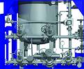
PetroChem pipe screen capture
Andy Redman, Process Engineering Director at Solutions Technology, explains his company's approach to the treatment of the P&ID.; "At Solutions Technology we have used MicroStation-based PlantSpace to change the P&ID; from a flat piece of paper with symbology to an entry point to a database containing a core of valuable information - every piece of information related to the plant."
Through PlantSpace, Solutions Technology is able to feed all design documentation into a core database, which is driven by the P&ID.; Database documentation includes specifications created in Excel spreadsheets, order documentation created in Microsoft Word and instrumentation diagrams in a variety of formats.
"What this means is that if you click on a line in the P&ID; the relevant characteristics are invoked," Redman continues. "All the symbols and characteristics that are on the P&ID; are registered on the database by their numbers, so you can click on the item in the diagram and from the database you can access any piece of information about that particular item."
The importance of creating a central and comprehensive database of relevant information, driven by the P&ID, is fundamental. Once the P&ID; has been created and reviewed, changes to the diagram become a critical issue. Designers need to keep a very accurate record of any changes to the design, which can be prompted through a second Hazop analysis or additional client reviews. Changes to the P&ID; carry with them serious operational and safety issues, and it is therefore vital that the P&ID; forms a central reference point for the entire project - a reference point where all changes and alterations are thoroughly documented.
Utilising PlantSpace, Solutions Technology have been able to implement a seamless information transfer process. Once the final P&ID; has been approved, the plant design is drafted in 3D, with the P&ID; forming the literal foundation of the 3D draft. With the P&ID; open on one screen and the 3D model on another, the designer is required to import all characteristics for the 3D design directly from the P&ID; - no elements can be created in 3D that do not already exist in the P&ID.; This means that drafting in 3D becomes a seamless process - one where the database of information contained in the P&ID; is automatically transferred to the 3D model.
The creation of the 3D model allows the plant designers to convey all basic civil, structural, piping and equipment layouts of the design in a rendered environment. This allows the client to view a virtual 'tour' of the plant, and also affords the project team a comprehensive overview of the plant design. Once the 3D model has undergone final review and analysis, isometric drawings are created from the model and passed on to the mechanical contractors, who then conduct the physical installation of the plant. The dimensioned drawings supplied to the contractors are produced directly from the 3D model, once again in a seamless information transfer process.
"One of the important things that we do is put the model on a laptop and send it to the site, along with the engineer supervising the construction,"says Redman. "In this way the model acts as a fundamental reference point for the construction team if any elements of the dimensioned drawings are unclear. We have had this seamless information transfer methodology in mind for a long time, but we were only able to implement the process when we started using PlantSpace in 1995, even though we tried before that to get it right," says Redman.
"At Solutions Technology we have always maintained that 'the process is king'. We are process engineers and we build process plants - therefore the discipline that must rule, is the process. The P&ID; forms the basis of chemical plant design, and the project is run from the diagram. With PlantSpace we have managed to crystallise our thinking as process engineers into an electronic document with a database attached. From this point on, the project can run smoothly, because there is a core of solid, good information driving the process."
Bentley Systems South Africa
(011) 462 5811
Others who read this also read these articles
The high-end MCAD and cPDm market segments of the PLM strategy
CIMdata considers the high-end MCAD market to include only those few CAD solution providers that deliver very comprehensive computer-aided design and analysis capabilities that are also tightly integrated with an enterprise-capable cPDm solution from the same supplier[ December 2005 ]
SA's prototype designers awarded
The SABS Design Institute is the driving force behind design promotion in the country through various award schemes, supporting innovation and entrepreneurship[ October 2005 ]
2D to 3D: the path to better products, faster and cheaper
Modern 3D CAD systems allow designers and engineers to edit a few parameters and automatically create the downstream deliverables for unique variants in minutes, instead of days or weeks[ October 2005 ]
ECL in Africa
ECL ensures a worldwide coverage of its client base through local service units which incorporate all the ECL know-how[ August 2005 ]
Catia brings business to South Africa
The fact that the A400M contracts were awarded to local enterprises is a strategic breakthrough for the South African aerospace industry[ August 2005 ]
Strand7 analyses the Beijing Water Cube
The latest Strand7 Release 2.3 has added the capability to take site specific seismic time histories and simply create equivalent spectral curves[ June 2005 ]
Pro/E versus SolidWorks
In summary, SolidWorks' swept surfaces and solids are more limited in their capabilities than Pro/Engineer's[ June 2005 ]
Northern Railway Extension receives green light
Windhoek Consulting Engineers was appointed as consulting engineers for the Northern Railway Extension, responsible for all aspects regarding the design and construction supervision of the total project valued at N$ 1,4 billion[ April 2005 ]
Others who read this also read these news items
Digitising a standard racing engine provides a springboard for future improvements
[ December 2005 ]
Nelson Mandela Metropolitan University leads the way with Catia V5
[ December 2005 ]
Integrated CNC solution for SA tooling industry
[ December 2005 ]
Accelerated design at Donkin Fans
[ December 2005 ]
PGF transforms its vision into reality
[ December 2005 ]
Defy introduces new product range
[ October 2005 ]
New Smarts for legal eagles
[ October 2005, Cadshop ]
Vectorworks scores with architects on ease of use
[ October 2005 ]
Others who read this also read these regulars
Search Site
Subscribe
Previous Issues
Other Technews Publications
Other Technews Buyers Guides
 |  | Copyright c1995-2009 Technews Publishing (Pty) Ltd.. All rights reserved. |