CAD/CAM trends in the automotive industry
April 2004
It is well known that worldwide the automotive industry is under significant pressure. Competition is forcing vehicle makers to reduce ‘time-to-market’ from the five years it took in the mid 1990s to the two years or less which are the targets today. The only way to bring about this drastic reduction in development time has been to introduce very high levels of standardisation and design and manufacturing automation, coupled with close collaboration throughout the whole supply chain. In this regard, computer integration of design and manufacturing has been proven for the ’24 month car’ to be achieved. There is no time in these tight schedules for extensive prototyping and testing – the majority of these processes have to be simulated in the computer. This ‘time-to-market’ reduction not only affects the vehicle makers (the OEMs), but everyone in the extended manufacturing process.
The most critical time-to-market window is the period between Class A styling freeze (the external appearance of the vehicle) to the delivery of the whole tooling design for production. In the new timescales this is typically of the order of 12 months. Much has been said and written about the CAD rationalisation exercises of the `Big 3' in the USA, but the emphasis is always placed on harmonising the approach to vehicle design - the front-end of the process - very little is mentioned about extending this approach into tooling design and production engineering. And yet in the critical time window between styling freeze and tooling delivery the same logic applies and the time savings are just as important.
Suppliers too have needed to embrace this standardisation and invest in advanced technology in order to stay in business. Many auto-makers are mandating to their supply chain, that the only way to do business, is by sharing information electronically.
In today's design environment there is no place for artificial walls between departments or functions let alone 'electronic walls' between computer systems. Integration has never been so critical: in a 2 year development cycle everything needs to be integrated at the outset and the design and manufacturing strategies already defined. There is no time for 'voyages of discovery' to develop post-processors or test new systems that have not been proven. All the problems have to be foreseen and resolutions developed otherwise the whole program suffers.
Drastic time savings of the order of 30-50% are made possible by using concurrent engineering techniques. The principle is simple; instead of sequential product design, development and manufacturing, the aim is to execute these processes in parallel or 'concurrently'.
The principle may be simple, but its implementation requires maximising collaboration and team working between functional groups from within a company, between companies in the supply chain and between supplier and customer. Usually the first step is to take down the existing physical walls between people and move them closer together, so that they can communicate more effectively. Eventually, as the whole industry globalises further, 'digital co-location' is the aim.
Even two decades after the early CAD harmonisation work was started at GM there is still a proliferation at the major OEMs of 'integration challenges' in production engineering and assembly line design. There has been a recognition in these areas that CAD harmonisation "does not apply to us - we are a special case - we need special systems - one-size-fits-all solid modelling is no good for line design". There was a time when some, if not all of these objections were valid - not any more.
The majority of the tooling design (some say up to 90%) is being initiated if not done by the supply chain. In this situation the supplier must be integrated into the overall concurrent engineering process if valuable time is not to be squandered.
Another worrying statistic is that during a car program, 50% of the jigs need to be redesigned. Previously, jigs and fixtures were designed and manufactured using standalone 2D drafting systems. Since they were not designed as 3D solid models in the same way that vehicle components are designed the majority of these jigs and fixtures have to be redesigned from scratch, potentially compromising tighter production schedules. More worrying still is the fact that because there is no overall tooling strategy in many organisations the same (or very similar) tooling is being designed and generated several times over in different locations and departments.
Using a 2D approach there is no associativity between the design of the part or the assembly, and since the jigs and fixtures data is delivered in 2D, they cannot be used in computer simulations of the assembly process. It is possible to redesign the jigs and fixtures in 3D using 2D data but this is extremely time consuming taking up to 20% of the OEM's process planning resources.
Fortunately the '2D only' approach is reducing in popularity, certainly for the OEMs and some Tier1 suppliers. But despite the use of 3D design and catalogues to promote standardisation at the component level, there is still no real standardisation at the cell level. Even at the component level, standardisation is still an issue in the supply chain. It is difficult for a user to select the appropriate standard for a specific OEM and it is all too easy to select an OEM non 'preferred standard'. Without an associative 3D approach, when the design changes, the designer has to reposition all the components manually because no automation is provided. There are no rules allowing checks that perform validations or compliance to company standards. This generates mistakes and costly delays.
In the current ad-hoc environment the engineer has complete freedom to choose the different components that make up the tooling design. In enlightened organisations once the components have been selected, the sketches are developed to produce the 3D models. If changes are required, it is necessary to go back to the original sketches in order to update.
In this way of working designers tend to drag and drop 'favourite' components without any reference to, or consistency with other designers. This leads to a proliferation of discrete 'unique' tooling. Moreover, due to this 'Lego' effect, significant numbers of non-standard components are generated together with standard ones.
As the design progresses each modification requires the engineer to roll back to the earliest stages in order to make the changes. The later these changes occur in the process the more expensive they are to implement (up to 10 times more in many cases).
In the same way that standardisation was introduced into vehicle design to save time and money, standardised or 'generic' tooling needs to be introduced into production engineering so that standard tooling can be adapted and modified quickly and effectively for each new product iteration. Also, if fundamental changes need to be made, when the underlying design has been done with state of the art technology like IBM's CATIA V5, it is possible to avoid these roll back conditions by automating the changes and so saving time and money.
CATIA V5 also has a technology called Knowledgeware, which runs in the background and helps users to adhere to company standards without having to specifically check for compliance. If a designer strays outside accepted 'best practice', Knowledgeware warns him and ensures that the design remains compliant. IBM has harnessed all these technologies to produce generative tooling design.
The word 'generative' in this context refers to the capability to produce new designs from a set of rules and components derived from previous designs. In some respects it is analogous to producing designs from a template or by 'morphing' old designs into new ones. It also means that the designs are 'associative' so that if the part changes the tooling can be updated automatically according to the design rules incorporated in the design. Moreover, it is possible to model to a 'dummy' part surface and then exchange it with the final part when it is available. The tooling can then be updated automatically. Such is the sophistication of Knowledgeware, if more towers are needed in a fixture they can be inserted and re-spaced automatically.
Generative tooling design is the practice of instantiating (or more simply copying) an existing, already validated toolset model, into a product and a process context. Once instantiated, these tooling models are adjusted to take into account the new physical context. This adjustment must be as fast as possible and above all, it must comply with technology rules. At the end of this process is a new validated toolset.
By a happy coincidence it is possible in CATIA V5 with Knowledgeware to build rules into components that allow them to adapt themselves automatically to the situation they are placed in, so much of the adjustment of each new instantiation can be achieved semi-automatically.
But generative tooling design is not just about geometry - it is about managing the intellectual property of the production engineering process to gain competitive advantage. Or to use the popular vernacular Generative Tooling Design is a major component in the broader PLM (product lifecycle management) context of automotive design and manufacture.
There is a huge element of master geometry that must be harnessed, there is also an over-arching data management and control task, which in IBM's case SmarTeam satisfies. Shop floor simulation using IBM's DELMIA product family is also critical.
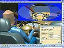
Because of the common V5 architecture IBM's assembly simulation tool (DELMIA) provides the ability to integrate with CATIA V5 design data in a native fashion without any data transfer, enabling easy collaboration and iteration between departments. Further, by double clicking a tooling design in the DELMIA environment, users can access the CATIA V5 geometry to modify the design. In situations where suppliers have native access to OEM data via SmarTeam this same level of collaboration can be propagated throughout the extended enterprise.
At its lowest level SmarTeam facilitates query/find operations for access to parts and assemblies. It also holds tracability information for ECRs and design changes through revisioning. It manages product catalogues and ensures data security and currency through vaulting mechanisms. Specific features co-ordinate supply chain design exchange through Briefcasing and synchronising data.
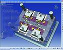
The essence of generative tool design is associative, knowledge-based data re-use with minimal re-design or modification. For a given BiW Design, a tool designer creates the jigs and fixtures design using the generative capability of CATIA V5. Pre-defined jigs and fixtures are instantiated and automatically configured - a bit like populating a flow chart with pre-defined data. Appropriate fingers and risers are selected and put into the configuration based on the input from your user and the geometric inputs. In this process, the tool design is already optimised because no extra manual 3D design is necessary, only re-configuration of existing tool design data.
One of the fundamentals of the CATIA V5 architecture is a concept called product process resources (PPR), which allows the exploitation of CATIA data across multiple dissimilar processes.
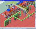
Once this initial tooling design step is achieved, the assembly simulation department recovers the tooling design, integrates it into the PPR environment and robots and other assembly machines are inserted as additional tooling.
Where engineering change orders are required by the line builder or there is a modification to the BiW, the tool design can be re-generated automatically under the generative tooling methodology. All the positioning and clamping tooling is repositioned and reconfigured without any manual 3D design and the underlying design rules are applied to ensure design consistency.
A sophisticated data management environment like SmarTeam is essential in this regard to identify previous similar projects, to manage the project schedule and resources, to distribute tasks through workflow mechanisms and to integration with project tools. It also allows users to understand the impact of an OEM design change on tooling and to determine the affected cells at all stages including design, simulation and documentation. Because of the richness of its attributes SmarTeam can also generate bill of materials respecting two different naming conventions (that of the OEM and the tooling supplier).
Some companies have already experienced the competitive advantage offered by CATIA V5 in jigs and fixture design.
According to MAN Trucks, an OEM: "With this software, we create fixtures faster and with higher quality. Thanks to earlier and more reliable decisions, we improved the robustness of our processes. The new methods release time for innovation, the decisive competitive advantage."
And Motoman, a supplier, said: "We collaborate better with our customers because we do more joint engineering. We can reduce our cost because our fixtures are right the first time. We save time by re-using and easily modifying existing parts. This was not possible in 2D. At the beginning, we had the feeling that we were some sort of pioneer, today we know that we have a competitive advantage."
Conclusion
The automotive customer has become more sophisticated and expects more standard features, more model variations, a cheaper purchase price and less time between new models. The whole industry is becoming more global as the leading vehicle makers attempt to reduce the number of their suppliers and negotiate world-wide agreements to reduce costs. The old adversarial relationships have given way to more alliances among makers and long term partnerships with suppliers.
R&D; is being shared between the vehicle makers and their suppliers. The supplier chain is now included in the 'concurrent engineering' practices of the vehicle makers. There is also a tendency for the suppliers to become sub-system suppliers, not just component suppliers. With this shift there is also a corresponding shift in design responsibility. Certain key Tier 1 suppliers now have responsibility for some of the 'packaging' in key parts of the vehicle.
The consequence of these trends is that suppliers are being persuaded to use the same software platforms as the vehicle makers so that they can take 'whole' vehicle information electronically, rather than the few surfaces that surround an isolated component.
Faced with either doing business with a limited number of vehicle makers or buying several sophisticated CAD/CAM systems the suppliers are looking towards systems that allow multiple CAD data formats to coexist. They are also seeking CAD solutions that are customised to their specific requirements. CATIA V5 satisfies both these criteria.
Many CAD users have developed their own data exchange mechanisms based on particular combinations of existing translators. To get to a point where a mechanism works even 95% of the time requires considerable effort and resources. If you need 100% reliable data exchange now, without this investment, the only safe mechanism is 'like for like' exchange.
The general availability of powerful, low cost computer hardware has meant that CAD/CAM is now more affordable than ever and so the prospective audience for CAD/CAM technology is wider than ever before. CATIA is a de facto standard in the automotive industry. The availability of affordable CATIA V5 solutions means that many small engineering 'job shops' further down the supply chain are now able to accept native CATIA data in electronic format and compete on equal terms with their larger competitors.
For more information contact local CATIA representative, Igal Filipovski, CDC (CNC Design Consultants), 011 786 3516, igal@cdcza.co.za, www.cdcza.co.za
Others who read this also read these articles
The high-end MCAD and cPDm market segments of the PLM strategy
CIMdata considers the high-end MCAD market to include only those few CAD solution providers that deliver very comprehensive computer-aided design and analysis capabilities that are also tightly integrated with an enterprise-capable cPDm solution from the same supplier[ December 2005 ]
SA's prototype designers awarded
The SABS Design Institute is the driving force behind design promotion in the country through various award schemes, supporting innovation and entrepreneurship[ October 2005 ]
2D to 3D: the path to better products, faster and cheaper
Modern 3D CAD systems allow designers and engineers to edit a few parameters and automatically create the downstream deliverables for unique variants in minutes, instead of days or weeks[ October 2005 ]
ECL in Africa
ECL ensures a worldwide coverage of its client base through local service units which incorporate all the ECL know-how[ August 2005 ]
Catia brings business to South Africa
The fact that the A400M contracts were awarded to local enterprises is a strategic breakthrough for the South African aerospace industry[ August 2005 ]
Strand7 analyses the Beijing Water Cube
The latest Strand7 Release 2.3 has added the capability to take site specific seismic time histories and simply create equivalent spectral curves[ June 2005 ]
Pro/E versus SolidWorks
In summary, SolidWorks' swept surfaces and solids are more limited in their capabilities than Pro/Engineer's[ June 2005 ]
Northern Railway Extension receives green light
Windhoek Consulting Engineers was appointed as consulting engineers for the Northern Railway Extension, responsible for all aspects regarding the design and construction supervision of the total project valued at N$ 1,4 billion[ April 2005 ]
Others who read this also read these news items
Digitising a standard racing engine provides a springboard for future improvements
[ December 2005 ]
Nelson Mandela Metropolitan University leads the way with Catia V5
[ December 2005 ]
Integrated CNC solution for SA tooling industry
[ December 2005 ]
Accelerated design at Donkin Fans
[ December 2005 ]
PGF transforms its vision into reality
[ December 2005 ]
Defy introduces new product range
[ October 2005 ]
New Smarts for legal eagles
[ October 2005, Cadshop ]
Vectorworks scores with architects on ease of use
[ October 2005 ]
Others who read this also read these regulars
Search Site
Subscribe
Previous Issues
Other Technews Publications
Other Technews Buyers Guides
 |  | Copyright c1995-2009 Technews Publishing (Pty) Ltd.. All rights reserved. |