CAD package gets hybrid design functionality enhancements
August 2000
Cadkey Parametrics was designed specifically for users wanting to improve on Cadkey’s hybrid design functionality and enhance their productivity with feature-based solid modelling and/or constraint-based sketching tools.
An independent user survey found that Cadkey users did not want to be forced into a parametric solid-only system nor give up the freeform design tools that they know. So Cadkey Parametrics was developed as an integrated enhancement product for those who can truly make use of the technology.
The software significantly expands the hybrid modelling approach with a high level of interaction between traditional 2D drawing, wireframe, freeform solid, surface and feature-based modelling. Functions in this new product can be accessed in a number of ways including hotkeys, icons, toolbars, classic mode and an optional new folder tree and pop-up menu system. The major time saving advantages to adding Cadkey Parametrics to a current toolkit can be separated into three benefit categories: feature-based modelling, hybrid parametric and sketching/constraining.
Feature-based modelling
Cadkey Parametrics makes editing solids easy, with full access to values used in each model's creation and interactions between sets of features and parts.
Changing the radius of a complex multi-edge fillet feature is as simple as selecting a blend face and typing in a new radius in the dialogue as shown in Figure 1. In this case the parametric fillet feature had been previously added to the imported nonparametric solid shown.
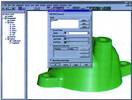
Figure 1. Editing a fillet feature
Changes to a group of parts with mating relationships such as the shaft, bushings and block (Figure 2) can easily be driven with a single variable. Updating mating parts this way saves time and more importantly, prevents errors that can result by editing each separately.
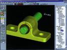
Figure 2. Four part assembly driven with one dimension
The creation of a set of prints for a family of parts can be automated by modelling and detailing a single parametric model. Adjusting the design parameters transforms the model and causes the layout to update automatically. This approach also prevents errors, saves the time in redrawing the other members of the family and allows changes to be propagated through the whole family, saving even more editing time.
Another advantage of feature-based modelling is suppression which significantly accelerates the display of large parametric models by temporarily turning off individual or categories of detail-level features, such as fillets or small holes that are unimportant to the visual clarity of the model.
Hybrid parametric
Typical midrange parametric solid modelling software forces users to completely rebuild legacy data in their own proprietary feature-based format before any changes can occur. Because of Cadkey Parametrics' hybrid abilities, there is no need to rebuild existing or imported solids. Parametric features can be added to and created from nonparametric solids. This integration still allows the nonparametric portions of a model to be edited with Cadkey's face modification functions.
Features such as the mould cavity (shown in Figure 3), formed by subtracting the volume of an imported nonparametric solid, will update automatically if the imported solid is replaced or modified. The position of features such as water lines dependant on the cavity will also update appropriately or provide feedback if conflicts arise. This capability allows contract manufacturers to quickly re-apply value-added changes to a customer's design if or when a new version is received.
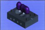
Figure 3. Parametric mould cavity created with an imported solid
Hybrid parametric modelling allows standard design features such as a bolt pattern for a model motor (shown in Figure 4), to be stored as a library of solids in industry-standard file formats like SAT, XT, STEP and IGES. This approach allows the library to be shared with other users and CAD systems.
Designers experienced in parametric modelling will appreciate that many complex models with hundreds of features become very difficult to work with due to congestion in the feature tree. In many cases significant numbers of design features do not require parametric editing or definition. Cadkey Parametrics provides a solution to these issues by allowing sets of features to be defined as a single nonparametric solid feature.
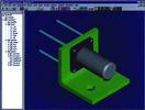
Figure 4. Creating features from a standard parts library
Sketching/constraining
Special sketching tools in Cadkey Parametrics offer major enhancement to the basic task of two-dimensional drawing and can be applied to more than just solid modelling.
Sketch entities and dimensions utilise animated 'click and drag' placement and editing capabilities resulting in improved visualisation and a reduced number of menu selections.
Dimensions and geometric constraints (like coincident, parallel, tangent and equal size) hold or drive the desired form of a sketch profile during editing. Ordinarily a sketch would be extruded or swept to generate a solid but not every part design or engineering task requires a 3D model. Sketching also provides a quick means of creating simple 2D drawings (see Figure 5). Intelligent associativity between 2D orthographic views can be constructed using constraints, so that changing the value of a dimension will update all views that are effected.
Figure 5. Dimension-driven and constrained 2D drawing
A constrained 2D sketch can be used in the study of multilink kinematic mechanisms. In the sketch (Figure 6), grabbing the link on the motor and dragging it in a circular path will animate the range of motion of the whole linkage.
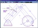
Figure 6. Animation of range of motion of linkage and motor
Existing or imported wireframe data can be quickly converted into sketches and automatically constrained. Years of legacy CAD data can be re-used in this manner to speed up the redesign process by aiding in the creation of adjustable parametric solid models.
Mecad Systems
(012) 665 1400
Others who read this also read these articles
The high-end MCAD and cPDm market segments of the PLM strategy
CIMdata considers the high-end MCAD market to include only those few CAD solution providers that deliver very comprehensive computer-aided design and analysis capabilities that are also tightly integrated with an enterprise-capable cPDm solution from the same supplier[ December 2005 ]
SA's prototype designers awarded
The SABS Design Institute is the driving force behind design promotion in the country through various award schemes, supporting innovation and entrepreneurship[ October 2005 ]
2D to 3D: the path to better products, faster and cheaper
Modern 3D CAD systems allow designers and engineers to edit a few parameters and automatically create the downstream deliverables for unique variants in minutes, instead of days or weeks[ October 2005 ]
ECL in Africa
ECL ensures a worldwide coverage of its client base through local service units which incorporate all the ECL know-how[ August 2005 ]
Catia brings business to South Africa
The fact that the A400M contracts were awarded to local enterprises is a strategic breakthrough for the South African aerospace industry[ August 2005 ]
Strand7 analyses the Beijing Water Cube
The latest Strand7 Release 2.3 has added the capability to take site specific seismic time histories and simply create equivalent spectral curves[ June 2005 ]
Pro/E versus SolidWorks
In summary, SolidWorks' swept surfaces and solids are more limited in their capabilities than Pro/Engineer's[ June 2005 ]
Northern Railway Extension receives green light
Windhoek Consulting Engineers was appointed as consulting engineers for the Northern Railway Extension, responsible for all aspects regarding the design and construction supervision of the total project valued at N$ 1,4 billion[ April 2005 ]
Others who read this also read these news items
Digitising a standard racing engine provides a springboard for future improvements
[ December 2005 ]
Nelson Mandela Metropolitan University leads the way with Catia V5
[ December 2005 ]
Integrated CNC solution for SA tooling industry
[ December 2005 ]
Accelerated design at Donkin Fans
[ December 2005 ]
PGF transforms its vision into reality
[ December 2005 ]
Defy introduces new product range
[ October 2005 ]
New Smarts for legal eagles
[ October 2005, Cadshop ]
Vectorworks scores with architects on ease of use
[ October 2005 ]
Others who read this also read these regulars
Search Site
Subscribe
Previous Issues
Other Technews Publications
Other Technews Buyers Guides
 |  | Copyright c1995-2009 Technews Publishing (Pty) Ltd.. All rights reserved. |